
Operational Amplifiers (Op-amps)
Introduction
Operational amplifiers, or op-amps, are widely used electronic devices in various applications. They are essential components in analog circuit design and signal processing.

Operational Amplifiers
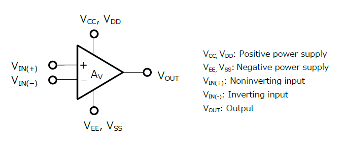
An operational amplifier, commonly referred to as an op-amp, is an electronic device that amplifies the voltage difference between its input terminals and produces an output voltage that is proportional to that difference. Op-amps typically have two input terminals: the inverting input (-) and the non-inverting input (+). The output is taken from a separate terminal.
Op-Amp IC Packet Types
Op-amp ICs typically come in various package types, such as:
- Dual Inline Package (DIP)
- TO 5-8 Metal Transistor
- Small Outline Integrated Circuit (SOIC)
Each package may contain one or multiple op-amps, depending on the specific IC design.

Ideal Op-Amps

An ideal op amp is defined as a differential amplifier with the following characteristics:
- Open Loop Gain (A): ∝ (infinite)
- Input Resistance: ∝ (infinite)
- Input Current: 0
- Output Resistance: 0
v1 = vo: This equation states that the voltage at the inverting input node (v1) of the operational amplifier is equal to the output voltage (vo). This is because the inverting input and output nodes are connected by a short circuit, meaning that any voltage at the output node will be directly present at the inverting input node.
v2 = v1 = vo: This equation states that the voltages at the inverting input node (v1), non-inverting input node (v2), and output node (vo) of an ideal operational amplifier are all equal. In an ideal op amp, there is no voltage difference between these nodes, and they are considered to be at the same potential.
i1 = 0 and i2 = 0: These equations indicate that the currents flowing into the inverting input node (i1) and non-inverting input node (i2) of the operational amplifier are zero. In an ideal op amp, the input impedance is considered to be infinite, meaning that no current flows into the input nodes.
i2 = 0: This equation specifically refers to the current flowing through the resistor Rs, which is connected to the non-inverting input node. Since the current into the non-inverting input node is zero, there is no current flowing through Rs.
vs - v2 = vs - vo: This equation represents the voltage across the resistor Rs, which is connected between the non-inverting input node and the ground (vs is the voltage at the non-inverting input node). The voltage across Rs is equal to the difference between the voltage at the non-inverting input node and the output voltage.
vs - vo = 0 or vs = vo: This equation follows from the previous equation and states that if the voltage across Rs is 0V (meaning no voltage drop across Rs), then the voltage at the non-inverting input node (vs) is equal to the output voltage (vo). In other words, the non-inverting input node of the op amp will maintain the same voltage as the output voltage.
An ideal op amp is a theoretical concept used as a reference point for analysis and design. It represents an op amp with characteristics that are perfect, without any limitations or imperfections. While real-world op amps have limitations, studying the ideal op amp provides a simplified model that helps engineers understand the fundamental principles and behaviors of these devices.

Types of Amplifiers
There are various types of amplifiers that utilize operational amplifiers for different applications. Some common types include:
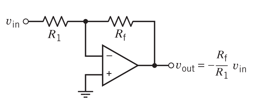
- Inverting Amplifier
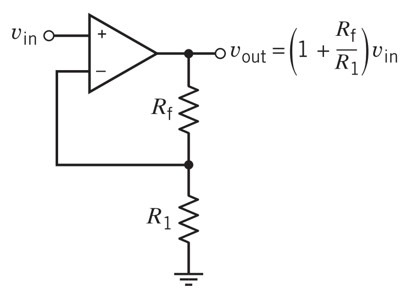
- Non-Inverting Amplifier
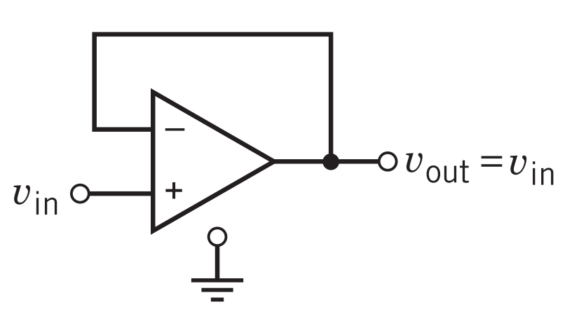
- Voltage Follower
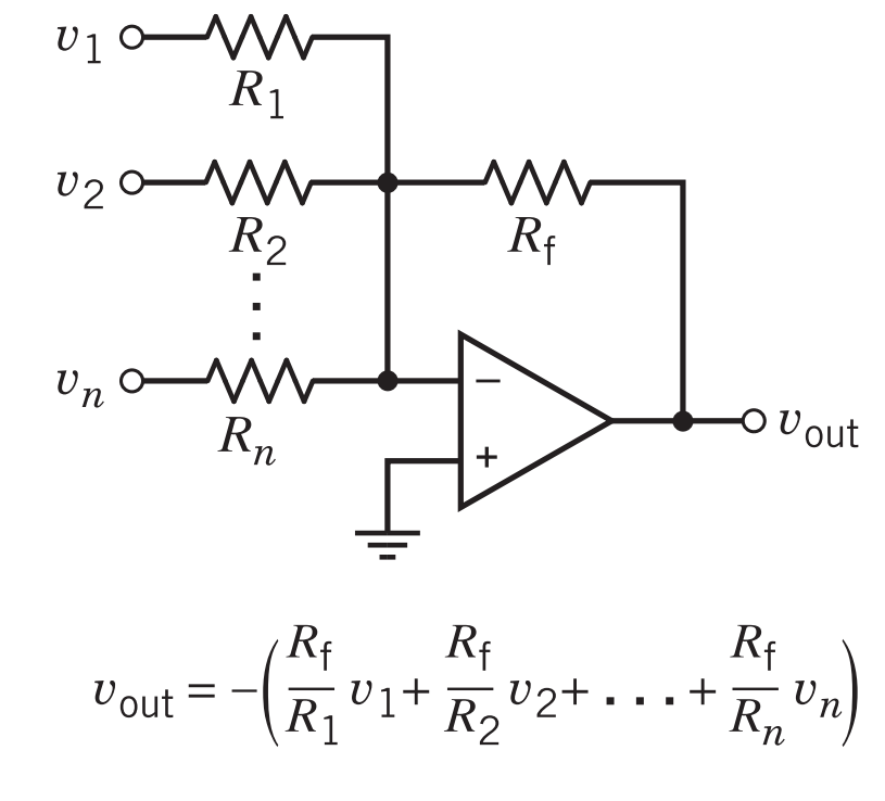
- Summing Amplifier
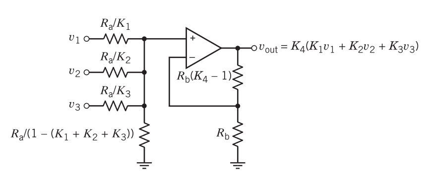
- Non-Inverting Summing Amplifier
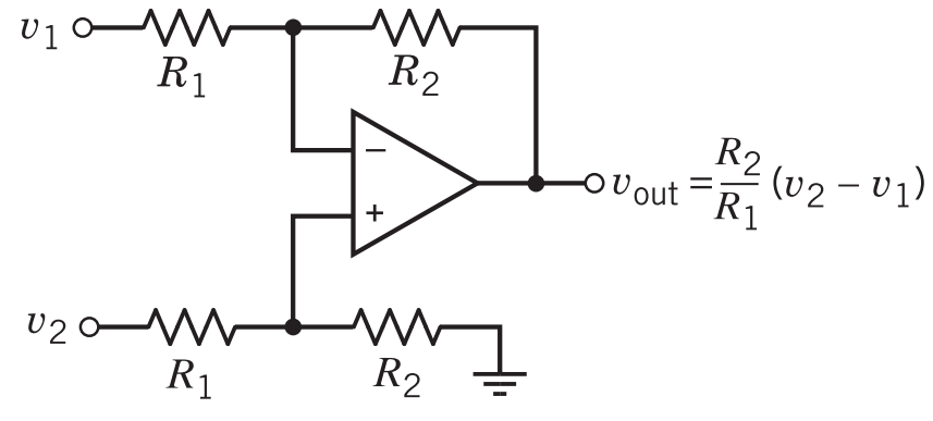
- Difference Amplifier
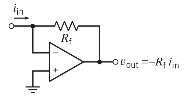
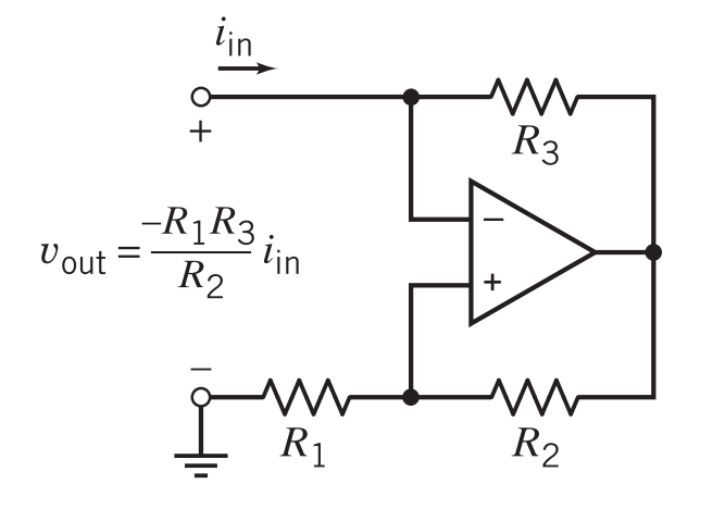
- Current-to-Voltage Converter
- Negative Resistance Converter
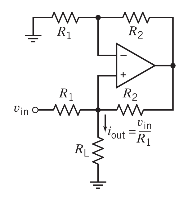
- Voltage-Controlled Current Source (VCCS)
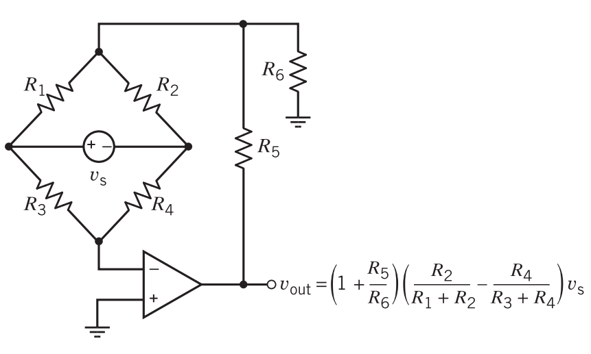
- Bridge Amplifier

Exercises and Simulations
Exercises and simulations are often used to reinforce understanding and practical skills in working with op-amps. These activities allow students to apply theoretical concepts and analyze circuit behavior.


Applications
Op-amps find applications in a wide range of electronic systems, including:
- 3-Input Mic Mixer Circuit
- Battery Level Indicator
- LED Volume Unit Meter
- Automatic Light Fence Circuit with Alarm
- IR Based Wireless Audio Transmitter and Receiver

Op-Amp Applications
1. 3-Input Mic Mixer Circuit
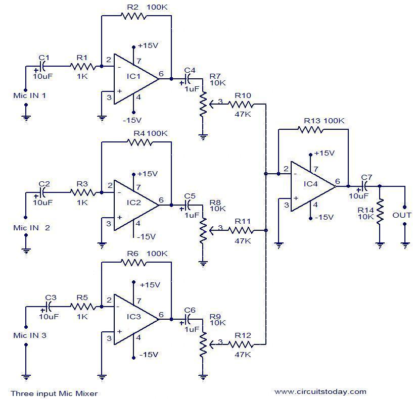
The project involves designing a 3-input microphone mixer circuit using operational amplifiers. The circuit utilizes four uA741 operational amplifiers, with IC1, IC2, and IC3 serving as preamplifiers for each microphone input. The preamplifiers are designed to provide a gain of approximately 40 dB for each input signal. IC4 is a summing amplifier that combines the outputs of the preamplifiers. The output of each preamplifier is connected to the inverting input of IC4 through an input resistor. This configuration allows for the mixing and combining of the microphone signals into a single output.
2. Battery Level Indicator
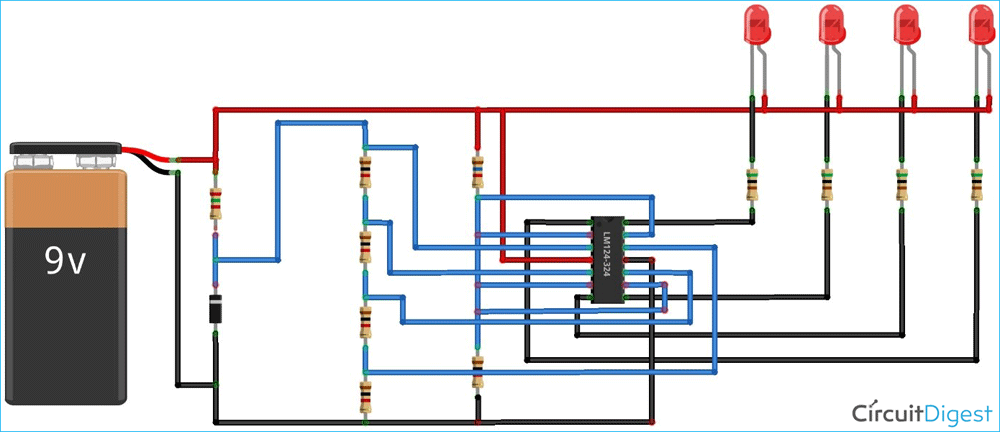
The project involves designing a circuit that uses LEDs to indicate the voltage level of a 12V battery. The main component used in the circuit is the LM324, a quad-operational amplifier IC. The circuit employs a voltage divider configuration to compare the battery voltage with predefined reference voltages.
Each op-amp within the LM324 is responsible for comparing the battery voltage with a specific reference voltage. The comparison results determine which LEDs light up. When the battery voltage is lower than the reference voltage for a particular op-amp, the corresponding LED illuminates.
The number of LEDs that light up provides an indication of the battery's charge level. This is achieved by setting predefined voltage thresholds for each LED. For example, if there are four LEDs, each LED may represent a specific voltage range such as 0-25%, 25-50%, 50-75%, and 75-100% of the battery's capacity. The LEDs light up accordingly depending on the battery voltage falling within these voltage ranges, giving a visual indication of the battery's charge level.
3. LED Volume Unit Meter
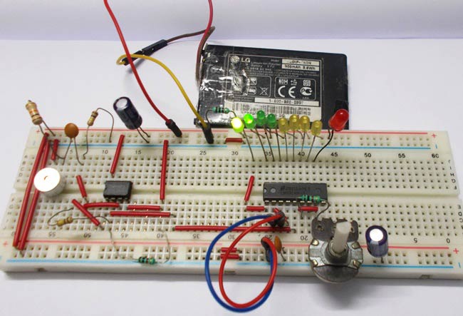

The LED Volume Unit (VU) meter project is designed to measure and display the intensity of sound using LEDs. The project utilizes several components to achieve this functionality.
Firstly, a microphone is used to capture the sound and convert it into corresponding voltage levels that are proportional to the sound's intensity. This voltage signal is then processed and filtered.
An LM358 operational amplifier is employed to amplify the filtered signal. The amplification process makes it easier to detect and measure the signal accurately.
To visualize the intensity or volume level of the sound, an LM3914 integrated circuit comes into play. The LM3914 compares the amplified signal to a reference voltage and controls the illumination of specific LEDs based on the comparison results. The number of LEDs that light up corresponds to the intensity of the sound being measured. Higher intensity or louder sounds will result in more LEDs being lit up, while softer sounds will illuminate fewer LEDs.
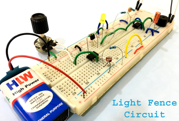
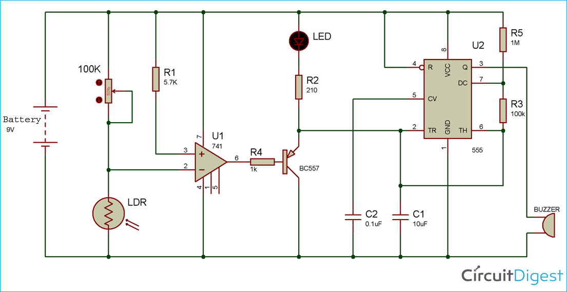
4. Automatic Light Fence Circuit with Alarm

The Automatic Light Fence Circuit with Alarm project utilizes an LDR, potentiometer, LM741 operational amplifier, PNP transistor, LED, and 555 timer to detect changes in light intensity and trigger an alarm. The LDR detects variations in light and converts them into changes in resistance. The LM741 compares the voltage from the LDR and potentiometer with a reference voltage, determining when the light intensity surpasses a threshold. When this happens, the PNP transistor conducts, lighting up the LED and activating the alarm. The LED provides a visual indication of activity detection. The 555 timer controls the duration of the alarm activation through a time delay. Overall, the circuit detects light changes, triggers an alarm, and provides visual feedback using various components.
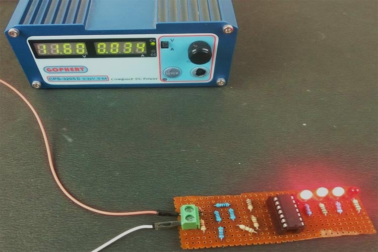
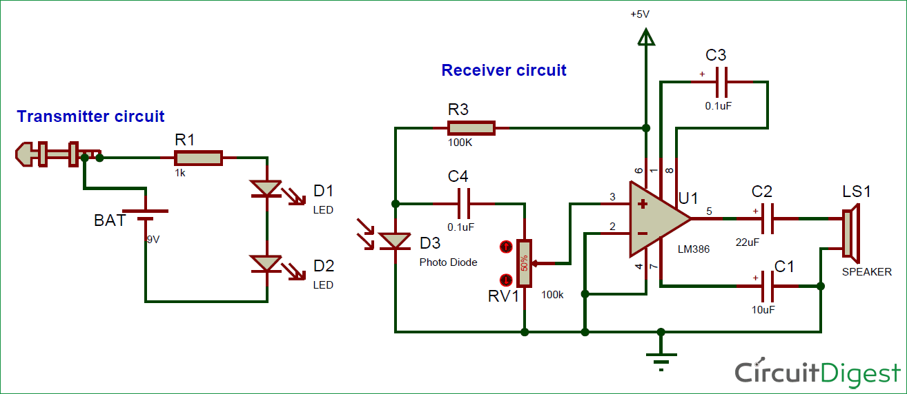
5. IR Based Wireless Audio Transmitter and Receiver
The project aims to create a wireless audio transmission system using infrared (IR) technology. The purpose is to enable the wireless transmission of audio signals from a source device, such as a smartphone or MP3 player, to a speaker without the need for physical cables.
The transmitter circuit is responsible for capturing the audio signal from the source device. It typically has an audio jack that connects to the audio output of the source device. The audio signal is then modulated onto the IR light emitted by IR LEDs. This modulation allows the audio signal to be carried by the IR light.
To enhance the transmission range of the system, two IR LEDs are commonly used instead of just one. The use of multiple LEDs helps to improve the strength and coverage of the IR signal.
On the receiver side, the circuit is designed to detect and extract the modulated IR signal. It utilizes a photodiode, which is a light-sensitive component, to receive the IR signal. The photodiode converts the received IR light variations back into an electrical signal representing the original audio.
To ensure that the audio signal is audible and suitable for driving a speaker, it undergoes amplification. The LM386 IC, a commonly used audio amplifier, is often employed for this purpose. It boosts the strength of the audio signal, making it suitable for driving speakers.
Finally, the amplified audio signal is outputted to a speaker, allowing the wireless transmission of audio from the source device to the speaker. The result is a simple and convenient wireless audio communication system that can be used for various applications, such as wireless speakers or short-range audio transmission.
For a visual demonstration of this presentation, you can watch the following video on YouTube: Operational Amplifier Analysis - ELECTROMAGNET THEORY SEMESTER 2


0 Comments